Comprehensive Ground Improvement Solutions
At Terra Melius, we engineer ground improvement systems that make challenging soil conditions build-ready.
We don’t believe in one-size-fits-all methods. Every project begins with understanding the ground, the risk, and the outcome you need—then applying the right technique with proven equipment, experienced teams, and quality-focused execution.

Vibro Compaction
Vibro Compaction is a ground improvement technique used to densify loose granular soils by rearranging soil particles into a denser state through depth vibration. The process is typically carried out using a vibrofloat suspended from a crane, allowing the treated ground to achieve improved bearing capacity and reduced post-construction settlement.
Vibro Compaction is especially valued for being environmentally friendly, efficient over large areas, and effective in improving overall soil performance for future construction.
%20(1).png)
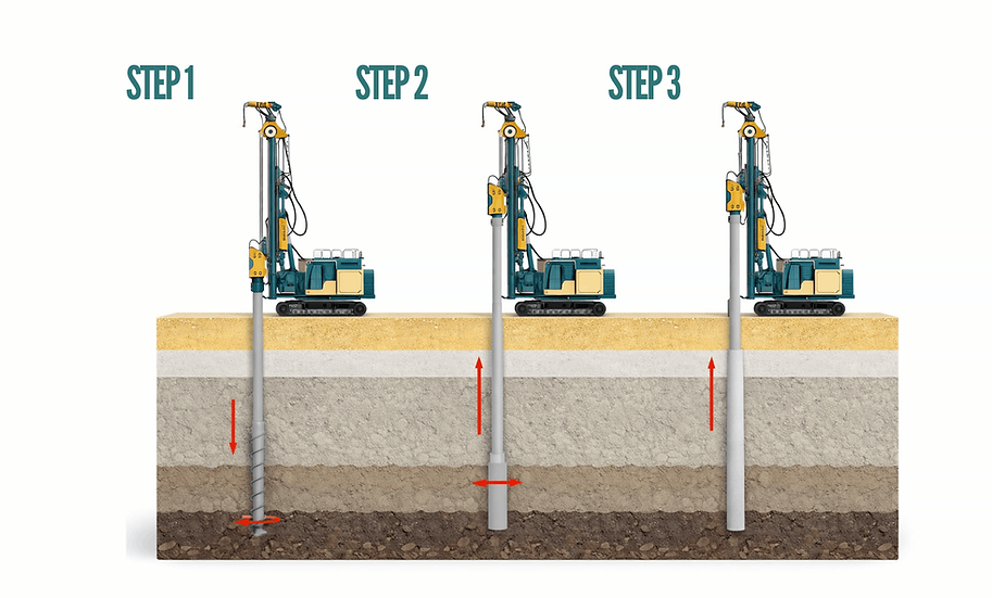
Step 1: Insert the vibroflot and “penetrate” the ground
-
A crawler crane lowers the vibroflot vertically at pre-marked grid points.
-
The probe penetrates under its own weight, assisted by water jetting from nozzles near the tip (this helps the probe reach depth and loosens the granular soil locally).
-
This sets up the soil for rearrangement—especially in loose sands / granular fills.
Process Of Vibro Compaction
.png)
Step 2: Compact by vibration
-
At the target depth, the vibroflot vibrates, causing sand/gravel particles to rearrange into a denser packing.
-
As the soil densifies, there’s a noticeable depression at the surface and an overall volume reduction (because voids reduce).
-
The probe is then worked upward in stages, continuing vibration so densification happens through the full treatment depth.
Step 3: Backfill/top-up and finish the grid
-
Because densification reduces volume, the surface depression is topped up with clean granular backfill (sand/gravel), typically fed continuously or in intervals.
-
The vibroflot continues compacting while the backfill is added, ensuring the treated column zone is fully densified.
-
The sequence is repeated point-by-point across the entire grid until the site reaches the required density/settlement performance and a level working platform is restored.
Advantages of Vibro Compaction
-
Reduces settlement significantly by densifying loose sand/granular soils, so the ground compresses less after construction.
-
Improves bearing capacity and stiffness, helping foundations perform better and often allowing more economical designs.
-
Fast and cost-effective for large areas, especially compared to switching to deep foundations when soil conditions are suitable.
-
Creates more uniform ground behavior, which lowers the risk of uneven/differential settlement across the footprint.
-
Can improve liquefaction resistance in loose, saturated sands by increasing density (site and design dependent).
Vibro Replacement
Vibro Replacement is used when the ground is too soft or silty/cohesive to be densified effectively through vibro compaction. Instead of only rearranging soil particles, this method creates load-bearing stone columns inside weak soil. The result is a composite ground system where the stone columns and surrounding soil work together to carry loads, reduce settlement, and improve overall stability.
It’s especially useful when you need ground improvement under embankments, slabs, tanks, or structures where soil strength is low, but a full deep foundation system may not be necessary.
%20(1).png)
Step 1: Insert the vibroflot and “penetrate” the ground
-
A crawler crane lowers the vibroflot at pre-marked grid points.
-
The probe penetrates to the design depth using vibration (and jetting if required), creating a cavity in the weak soil.
-
This step prepares the ground to accept stone and ensures the column is formed at the correct depth and location.
Process Of Vibro Replacement

Step 2: Feed stone
-
Clean crushed stone / gravel is fed into the cavity.
-
The vibroflot compacts the stone in controlled layers (lifts) as it gradually works upward.
-
This repeated “add stone → compact → lift” cycle creates a dense, load-bearing stone column that interlocks with the surrounding soil.
Step 3: Complete the grid
-
The same sequence is repeated point-by-point across the full layout grid.
-
Once completed, the ground behaves as a composite system: stone columns + native soil share the load.
-
Final levels are restored with top-up material if required, and the improved ground is ready for foundations/formation works.
Advantages of Vibro Replacement
-
Effective in soft/cohesive soils where vibro compaction is not suitable (soils that won’t densify properly).
-
Reduces both total and differential settlement by creating a stronger, more consistent ground system under the footprint.
-
Improves bearing capacity and stiffness, allowing heavier loads or more economical foundation solutions compared to untreated ground.
-
Provides drainage pathways through the stone columns, which can accelerate consolidation and improve performance in saturated soils.
-
Can improve liquefaction resistance and seismic performance in certain ground conditions (site-dependent).
-
Often faster and more cost-efficient than deep foundations for many medium-to-heavy load projects, especially over large areas.
Rigid Inclusions
Rigid Inclusions are used when the soil is soft/compressible and you need strong settlement control, but you still want to keep the project in a ground improvement + shallow foundation approach (instead of switching fully to deep piles).
Unlike vibro methods, rigid inclusions do not densify the soil through vibration. They create a field of stiff concrete columns installed in a grid. Above these inclusions, a Load Transfer Platform (LTP) (engineered granular layer, often with geogrid) spreads the structure load so the system behaves as load-sharing: part of the load goes to the inclusions, and part remains on the soil. This is exactly why rigid inclusions are chosen when settlement criteria are tight.
%20(2).png)
Step 1: Drill/penetrate to depth
-
A piling rig positions over the marked grid points and penetrates to the required depth using a CFA (continuous flight auger) or a displacement tool.
-
This is a controlled operation: depth and verticality are monitored so each inclusion is formed exactly where the design requires.
-
The ground is not “shaken” like vibro methods—this step is about creating the path for a stiff column with precision.
Process Of Rigid Inclusions
Step 2: Pump Concrete
-
At depth, unreinforced concrete is pumped through the hollow stem of the auger.
-
As the auger is slowly withdrawn, pumping continues so the inclusion forms continuously from the bottom up.
-
This controlled extraction + pumping sequence is what ensures continuity, consistent diameter, and reduces risk of voids or collapse—your column is essentially “cast in place” as the tool comes out.
Step 3: Build the load-sharing system
-
The same cycle is repeated across the full site until the complete inclusion grid is installed.
-
Then a Load Transfer Platform (LTP) is constructed above: compacted granular material (often with geogrid/geotextile) that spreads loads.
-
Once the foundation/raft sits above the LTP, the structure load is distributed so the system works as designed: rigid inclusions carry a higher share due to stiffness, while soil still carries part—resulting in strong settlement control without needing full deep piles.
Advantages of Rigid Inclusions
-
Excellent settlement control because grout/concrete inclusions are much stiffer than stone columns or untreated soil.
-
Improves bearing capacity in very soft or compressible ground while still allowing shallow foundations in many cases.
-
Minimal vibration, making it ideal near existing structures, utilities, and sensitive areas.
-
Efficient over large footprints, especially where deep piles would be excessive or too costly.
-
Highly controlled installation, with measurable parameters (depth, volume, pressure) that support quality assurance.
-
Flexible design system: spacing, depth, and LTP design can be tuned to hit specific performance targets.
Bored Piles
Bored piles are used when the structure loads are too high for shallow foundations and the near-surface soils cannot carry those loads without excessive settlement or stability risk. In this system, the pile itself becomes a structural foundation element—it transfers load to deeper, stronger ground through a combination of end bearing (at the toe) and skin friction (along the pile shaft).
Terra Melius notes that the most common type in the region is bored cast-in-place piles (cast in situ)—meaning the pile is formed on site by drilling and concreting, not by driving a pre-made pile.

Step 1: Drill the borehole
-
A rotary piling rig drills a large-diameter hole to the required depth using a drilling bucket/auger tool.
-
If the soil is loose, sandy, or groundwater is present, the borehole is stabilized with temporary steel casing (as Terra Melius typically follows) so the sides don’t collapse.
-
This step focuses on achieving correct depth, diameter, and verticality while keeping the hole stable and clean for the next stages.
Process Of Bored Piles

Step 2: Install the reinforcement cage
-
A steel reinforcement cage is lowered into the drilled hole inside the casing.
-
The cage provides structural strength where required—especially for piles that must resist lateral forces, bending, uplift, or demanding durability conditions.
-
The cage is positioned accurately (alignment + cover) to ensure the pile performs as a true structural member, not just a “filled hole.”
Step 3: Pile completion
-
Concrete is placed from the bottom up using a tremie pipe (a pipe that reaches near the bottom), ensuring proper concreting even in wet conditions and preventing segregation.
-
As concreting progresses, temporary casing is withdrawn in a controlled manner so concrete replaces the supported zone and forms a continuous pile shaft.
-
After curing, the finished bored pile becomes a deep foundation element that safely carries heavy loads to depth.
Advantages of Bored Piles
-
Handles very heavy loads confidently by transferring them to deeper, stronger strata (end bearing + skin friction).
-
Bypasses weak surface soils, so the foundation performance is not limited by soft upper layers.
-
Highly customizable — pile diameter, depth, and reinforcement can be designed to match the exact structural requirements.
-
Strong structural reliability with reinforcement cages, making it suitable for lateral loads, uplift, and bending conditions.
-
Works well in constrained sites (urban/infrastructure projects) because drilling and placement can be controlled precisely.
-
Consistent quality control is possible through controlled drilling depth, bore stability methods (casing), and tremie concreting procedures.
Business Info
Terra Melius delivers ground improvement and piling works across the UAE—helping projects reduce settlement risk, improve bearing capacity, and move faster through disciplined execution, strict HSE culture, and testing-led verification.
Workshop Adress
Al Madam Street - Al Madam - Sharjah, UAE
Workshop Hours
Mon to Saturday
8am to 5pm
Office Adress
Office no. 210, Al Mazar centre, Hor al anz, Dubai - UAE
P.O.BOX 93770
Office Hours
Mon to Saturday
9 am To 5 pm